
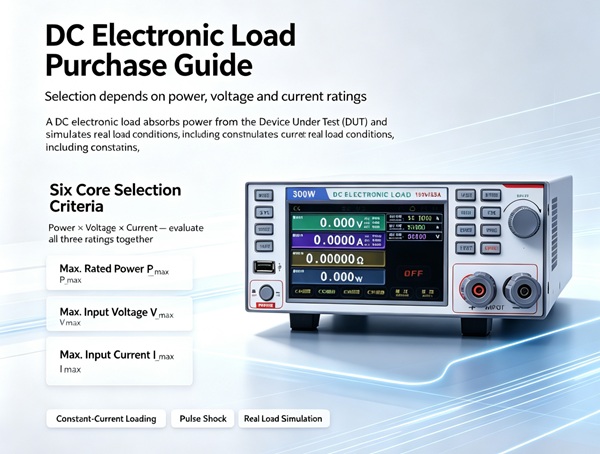
DC Electronic Load Procurement Guide
A DC electronic load is essentially a controlled power-consuming device. Instead of drawing power from the grid, it absorbs DC power output by your Device Under Test (DUT), and simulates various load operating conditions in a programmable manner — constant current loading, pulse impact, dynamic switching, etc.
Six Core Key Indicators for Model Selection
- Power × Voltage × Current — All Three Parameters Must Be Evaluated Together
This is where most buyers make mistakes. You may think a 300W load is sufficient, yet find your 60V/5A power supply cannot reach 5A loading. The reason is that the maximum current of this load at 60V is only 3A.
You need to check the common operating range of the three maximum limits one by one:
- Rated power of the load: P_max
- Maximum input voltage of the load: V_max
- Maximum input current of the load: I_max
Then cross-reference with your DUT:
- Maximum output of DUT: V_dut, I_dut, P_dut
- Requirements: V_max > V_dut (reserve a margin of 10~20%), I_max > I_dut, P_max > P_dut
- In engineering practice, the rated power of the load is generally set to 1.2~1.5 times the DUT power to avoid long-term full-load operation.
Special attention should be paid to whether full-current loading can be achieved at low voltages (low-voltage operating characteristics / derating curve). Many high-power loads have a very low upper voltage limit under high-current gears.
- Accuracy and Resolution — Do Not Confuse “Resolution” with “Accuracy”
Two indicators will be listed on the specification sheet:
| Concept | Expression | Key Focus Point |
| Accuracy | ±(% Reading + % Full Scale), e.g. ±(0.05%RD + 0.05%FS) | Determines whether test data can be used for official reports |
| Resolution | Minimum configurable/display step, such as 1mV / 1mA or 0.1mV / 0.1mA | Determines how finely parameters can be adjusted |
- R&D & certification testing: Accuracy better than 0.05%~0.1% is recommended, with a minimum resolution of 1mV/1mA; 0.1mV/0.1mA is preferred.
- Quick production line inspection: Accuracy can be relaxed, but the stability of protection trigger thresholds (OVP/OCP) must be reliable.
- Dynamic Response Speed (Slew Rate / Rise Time) — Critical for Power Supply Dynamic Testing
If you need to test DC-DC transient response and OCP switching speed, the current slew rate of the load directly determines the authenticity of test results:
- Entry-level / static production line testing: A/ms grade is sufficient.
- Professional dynamic testing: Prioritize A/μs grade indicators; high-quality mainstream instruments reach 2~5 A/μs or higher.
Dynamic switching frequency: Refer to the nominal value on the datasheet. Most programmable loads range from over ten kHz to 25~50 kHz.
- Heat Dissipation Mode and Continuous Loading Capacity — Determines Long-Term Aging Test Performance
Electronic loads convert power consumption into heat. Poor heat dissipation leads to increased temperature drift, unstable data, and frequent protective shutdowns.
Focus on three items:
- Heat dissipation structure: Air cooling (front air outlet / side air outlet) or water cooling / regenerative type. Regenerative loads are preferred for large systems to save electricity costs.
- Derating curve: Verify if full rated power can be maintained under high-temperature environments (e.g., 40°C in laboratories during summer).
- Continuous operation reliability: Aging tests impose strict requirements on fan service life and temperature uniformity.
- Protection Functions — Lack of Protection May Cause Costly Equipment Damage
The following protection functions are mandatory:
| Protection Function | Importance |
| OVP / OCP / OPP (Over Voltage / Over Current / Over Power) | Prevents damage caused by DUT malfunction |
| OTP (Over Temperature Protection) | Prevents burnout of the load itself |
| Reverse Polarity / Reverse Connection Protection | Avoids smoke and damage when testing batteries with reversed wiring |
| Local Sense / Remote Sense | Compensates line loss under high-current conditions |
Reverse polarity protection and UVP (Under Voltage Protection) are particularly critical for testing batteries, power batteries and charging piles.
- Interfaces and Automation Ecosystem — Insufficient Interfaces Will Force Equipment Replacement Later
Modern testing cannot rely solely on manual knob adjustment. Confirm the availability of at least two of the following:
- USB / LAN (LXI) / GPIB
- SCPI command set support
- Matched PC software or Python/MATLAB drivers
- Data logging, sequence testing, automatic Go/No-Go judgment